Electric Cooling Fan Kit
Below is a brief synopsis of my senior capstone project. We work along side automotive aftermarket manufacturer Flex-A-Lite to develop their latest electric cooling fan kit.

Design Brief

The project kicked off with identification of the constraints and criteria, along with a break down of the project goals. The design process was initiated by establishment of key parameters.

Needs, Metrics, Benchmarks and Functions
The following were established and run through House of Quality Matrices to weight importance of design parameters.
Data Collection

Signal output from data collection run.
Fan Speed Sensor
PCM Variable Relay
Signal Return
Switched Ground
Reference Voltage.
Data collection was performed by using a variety of software in congruence while conducting a heat soak test on the benchmark vehicle.
Picoscope 6 was used to collect signal outputs.
Auto Enginuity monitored the PCM for and diagnostic trouble codes
After review, it was discovered that the OEM fan speed sensor communicated via a simple square wave which would have to be emulated with a microcontroller.


Concept Generation

Concept Gneration
Samples of concept ideas from initial brainstorming sessions.
A brainstorming session led to the birth of ten concepts for the microcontroller. These concepts were submitted as layouts and logic diagrams.
Next, a Concept Screening Matrix was used to identify the leading concepts and move them forward in the design process.

Concept Selection
The concepts were narrowed down to the two most promising configurations, A and I respectively. Both concepts were moved into the development phase and initial mock ups were made for PCB board designs and the logic functions were tested via Lab View software.

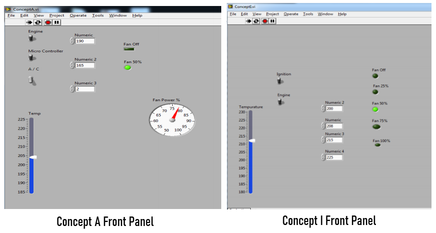
Concept A
Concept A tried to create a logic function that simulated continuous ramp up of the cooling fan speed as engine temperature increased.
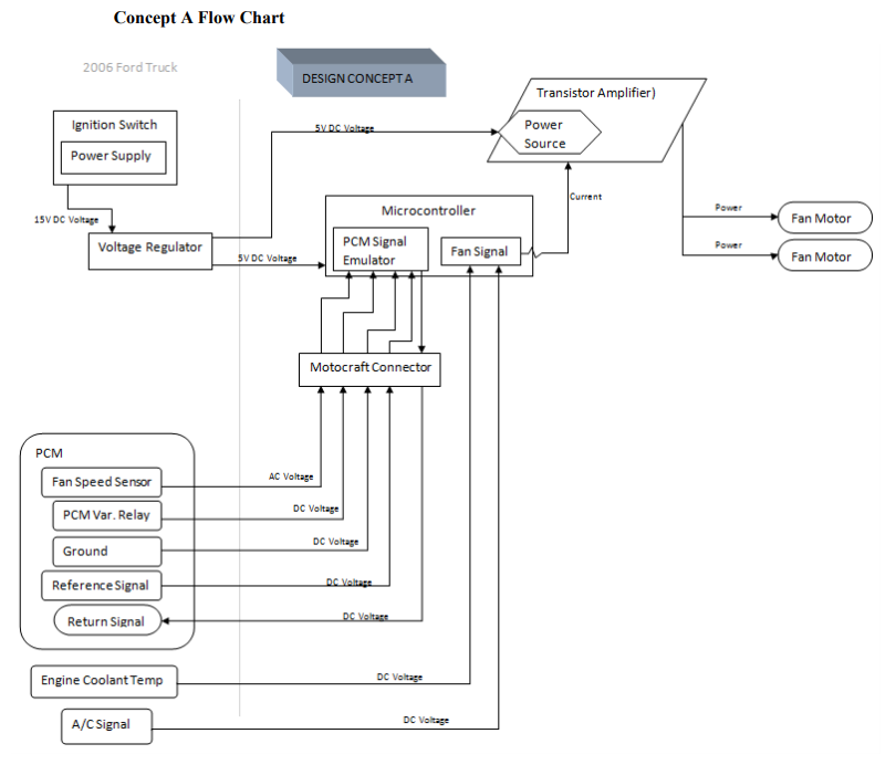
Concept A Flow Chart

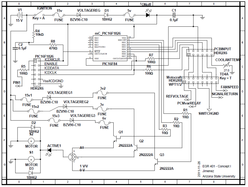
Concept A Circuit Design
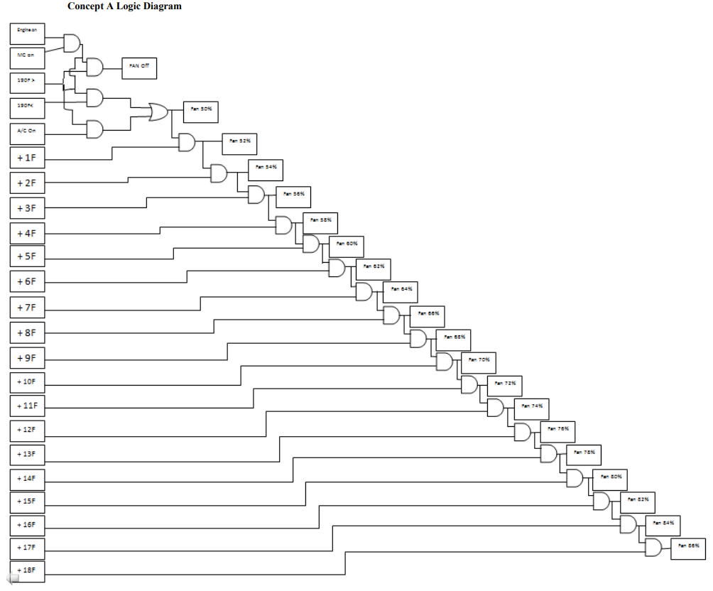
Concept A Logic Diagram
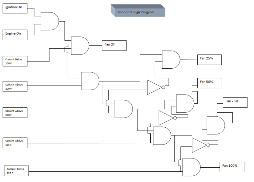
Concept I
Concept I tried to use a logic function that stepped fan speed up in 25% increments as engine temperature rose.

Signal Emulation

Testing was performed on the OEM fan clutch to determine parameters of the current electrical system.

A bread board and oscilloscope was used to develop a circuit that would accurately emulate the needed square wave.
Prototyping
Discussion with the customer led to a final selection of a combination of concepts A and I. The microcontroller would turn the fan on 100% when the engine temperature signal triggered threshold. As the engine temperature lowered, the fan would then switch off below threshold.

The initial prototype for the fan speed sensor microcontroller was based off of the customers previous designs. It made use of a printed PCB board encased in a plastic housing with a plug for the fan speed sensor socket.
Results

Dynamometer Test
Type: Dynapack
Vehicle: 2006 Ford F-350 Super Duty 6.0L Powerstroke Diesel
Parameters:
Gear: 3 Throttle: 80%
Benchmark Results:
Horsepower: 315 bhp Torque: 460 ft-lbs
Prototype Results:
Horsepower: 350 bhp Torque: 560 ft-lbs
Measurables:
The prototype cooling fan replacement kit demonstrated a measurable improvement of 42 bhp and 70 ft-lbs of torque at 80% throttle in third gear.
No significant improvement in fuel economy was measured.
Full Report
Below is a link to ta copy of the full project report and analysis.